Aparna Rollform

Cable Tray Manufacturing Process: From Steel Coil to Finished Tray

cable tray manufacturing process

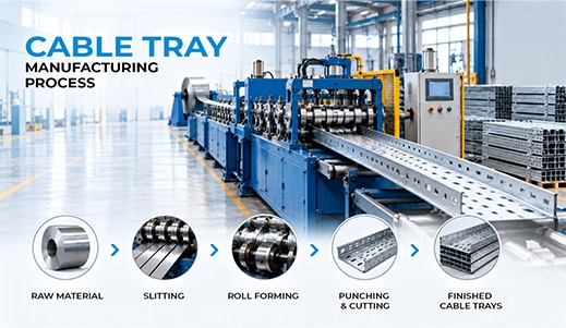
The cable tray manufacturing process converts flat steel coil into a finished, corrosion-protected cable support system through a controlled sequence of stages: raw material selection, decoiling and levelling, punching or perforation, roll forming, cutting to length, welding and assembly, surface treatment, inspection, and packing.

For an engineer, contractor or procurement professional, this is not academic detail. Almost every problem that shows up on site — a tray that sags between supports, edges that rust within two monsoons, sections that will not align at a joint — traces back to a specific decision made in one of those stages. Understanding the process is what lets you read a supplier’s datasheet properly, ask the questions that actually matter, and tell a genuine manufacturer from a trader repackaging someone else’s output.

This guide walks through each stage in sequence, explains the two manufacturing routes used in the industry and why the choice matters, and covers the one sequencing decision — when galvanising happens — that has more effect on service life than any other single factor.

Key Takeaways

  • Cable trays are made in nine stages, from steel coil selection to packing and dispatch.
  • Volume production uses continuous roll forming from coil; press-brake fabrication is used for small batches and non-standard sections.
  • Perforation is punched before forming, not after — punching a formed profile is slower and less accurate.
  • Pre-galvanised and hot-dip galvanised trays differ in when the zinc is applied, and that single sequencing difference determines whether cut edges and welds are protected.
  • Quality is built in at every stage, not inspected in at the end — the checks that matter most happen before the tray is formed.

What Is the Cable Tray Manufacturing Process?

The cable tray manufacturing process is the sequence of operations that turns raw steel, aluminium or stainless steel into finished cable trays ready for installation. A modern plant runs it as a continuous production line rather than a set of separate workshop tasks: coil feeds in at one end, and cut, formed, perforated tray sections come off the other.

The full sequence looks like this:

  1. Raw material selection and inward inspection
  2. Decoiling and levelling
  3. Punching and perforation
  4. Roll forming
  5. Cutting to length
  6. Welding and assembly (for ladder types and accessories)
  7. Surface treatment — galvanising, powder coating or painting
  8. Quality inspection and testing
  9. Packing and dispatch

Each stage is covered in detail below. The order matters: several stages cannot be resequenced without either raising cost or reducing quality, and one of them — surface treatment — has two valid positions in the sequence that produce genuinely different products.

Stage 1: Raw Material Selection

Everything downstream is constrained by what enters the plant. A tray cannot be stronger, flatter or more corrosion-resistant than the coil it was formed from, which is why material selection and inward inspection are the first real quality gate rather than a procurement formality.

Materials Used in Cable Tray Manufacturing

Material

Characteristics

Typically specified for

Mild steel (black / CR coil)Highest strength-to-cost; requires a protective finish after formingGeneral industrial use where trays will be hot-dip galvanised or powder coated after fabrication
Pre-galvanised steel (GP coil)Zinc coating already applied to the coil at the mill; formed after coatingIndoor and moderately protected environments; fast turnaround, economical
AluminiumRoughly a third the weight of steel, naturally corrosion resistant, non-magneticWeight-sensitive installations, rooftops, marine and coastal sites, instrumentation runs
Stainless steel (SS 202 / 304 / 316)Highest corrosion resistance; 316 handles chlorides and chemical exposurePharmaceutical, food processing, chemical plants, offshore and coastal installations
FRP / fibreglassNon-conductive and chemically inert; no galvanic corrosionHighly corrosive chemical environments and locations where metal is unsuitable

What inward inspection should cover: mill test certificates confirming the steel grade, actual sheet thickness measured rather than assumed, coating mass on pre-galvanised coil, and surface condition. Sheet thickness is the one buyers most often get short-changed on — a tray rolled from coil 0.2 mm under specification looks identical and costs the manufacturer noticeably less, but it will not carry the load the datasheet claims.

Stage 2: Decoiling and Levelling

The selected coil is loaded onto a decoiler that feeds it steadily into the line. Before anything is punched or formed, the strip passes through a levelling unit — a series of staggered rollers that flatten out the residual curvature the steel acquired from being wound into a coil.

Levelling sounds trivial and is not. Steel carries internal stress from coiling, and if that stress is not relieved before forming, it reappears afterwards as bow, twist or camber in the finished tray. A tray with camber will not sit straight on its supports, and two such trays will not align cleanly at a coupler joint. Installers on site describe this as trays that “fight” each other — the cause is almost always inadequate levelling at the plant.

Stage 3: Punching and Perforation

The levelled strip is then punched. This creates the slot pattern in perforated trays, the fixing and coupler holes in every type, and the rung slots in ladder side rails.

Punching happens before forming, not after, and this is one of the clearest markers of a properly engineered production line. Punching a flat strip is fast, accurate and repeatable, and the tooling registers the pattern precisely against the strip edge. Punching a profile that has already been formed means working around the bends, which is slower, harder to hold in tolerance, and tends to distort the section. Some small fabricators do it that way because it needs less tooling investment — but the hole positions drift, and holes that drift are why site teams end up drilling fresh ones.

The perforation pattern itself is a design decision, not decoration. More open area improves heat dissipation around the cables and reduces tray weight; less open area leaves more material and therefore more strength. The pattern is chosen to balance those two against the tray’s intended load class.

Stage 4: Roll Forming

Roll forming is the stage that gives the cable tray its shape and its strength. The punched flat strip passes continuously through a series of paired rollers, each set bending it slightly further than the last, until the flat strip has become a C-section, a channel or a side rail with the required flange height.

The bending is deliberately gradual — a typical cable tray profile is formed over many roller stations rather than a few. Forming steel too aggressively at any one station work-hardens and can crack the material at the bend radius, and produces spring back that pulls the section out of tolerance. The number of stations, the roller profile design and the line speed together determine whether the finished section holds its dimensions consistently along its whole length and from one batch to the next.

Why the formed shape matters more than the sheet thickness alone: a flat strip of steel has almost no bending stiffness. Fold the same strip into a C-section with returned flanges and it becomes a structural member, because the material has been moved away from the neutral axis. This is why two trays of identical sheet thickness can have very different load capacities — the profile geometry, flange height and edge return do more work than the thickness figure buyers tend to focus on.

Stage 5: Cutting to Length

As the formed section emerges from the last roller station, it is cut to the required length — commonly 2.5 metres or 6 metres for standard supply, with custom lengths produced to order.

Modern lines use a flying cut-off that travels with the moving section and shears it without stopping the line, which keeps production continuous and the cut square. The two things that matter here are length consistency (out-of-tolerance lengths create cumulative alignment problems across a long run) and cut quality — a ragged or burred cut edge is both an installer hazard and, on pre-galvanised material, a corrosion starting point.

Stage 6: Welding and Assembly

Perforated and solid-bottom trays emerge from roll forming essentially complete. Ladder trays do not: they are assembled from two roll-formed side rails joined by rungs, and that joining is done by welding.

Rungs are positioned at the specified spacing — closer spacing gives more support points for smaller cables, wider spacing suits heavy power cables and reduces weight — and welded to both side rails. On production lines this is typically resistance or MIG welding, often on a fixture that holds the rail spacing and rung alignment while the welds are made.

Weld quality is a structural matter here, not a cosmetic one. The rung-to-rail weld is what transfers the cable load from the rungs into the side rails; a weak or incomplete weld becomes the failure point long before the steel itself is stressed. Welds should be continuous where specified, free of undercut and porosity, and the spatter cleaned off — spatter left on the surface becomes a coating defect at the next stage.

Accessories — bends, tees, crosses, reducers, risers and couplers — are fabricated in this same stage, using formed sections cut and welded to the required geometry. A manufacturer that produces its own accessories in matching material and finish is a meaningfully different proposition from one that buys them in, because the match in thickness, finish and hole pattern is what makes a system assemble cleanly on site.

Stage 7: Surface Treatment

Surface treatment determines how long the tray survives in its environment. It is also the stage where manufacturers differ most, and where the sequence — whether the protective coating goes on before or after forming — matters more than most buyers realise.

Pre-Galvanising (GI / GP)

Pre-galvanised trays are roll formed from coil that was already zinc-coated at the steel mill, by a continuous hot-dip process. The coating is uniform, and the production route is fast and economical, because no separate coating operation is needed after forming.

The trade-off is at the edges. When a pre-galvanised coil is cut and punched, the freshly exposed cut edges and hole edges have no zinc on them. Zinc does provide some sacrificial protection to small exposed areas nearby, but pre-galvanised trays are best specified for indoor and reasonably protected environments rather than aggressive or coastal exposure.

Hot-Dip Galvanising (HDG)

Hot-dip galvanising is applied after the tray is fully formed, punched and welded. The finished tray goes through a chemical preparation sequence — degreasing, acid pickling to remove mill scale and oxide, rinsing, and fluxing — and is then immersed in a bath of molten zinc. The zinc reacts metallurgically with the steel surface to form bonded zinc-iron alloy layers.

Because the tray is dipped after fabrication, every surface is coated: outer faces, inner faces, cut edges, punched hole edges and welds. That complete coverage is precisely why HDG is specified for outdoor, coastal, humid and industrial environments, and why it typically carries a substantially heavier coating than pre-galvanised material.

Powder Coating

Powder coating applies an electrostatically charged dry polymer powder to the tray, which is then cured in an oven to form a continuous film. It gives a hard, uniform finish in any colour and is often applied over a galvanised base in what is called a duplex system — zinc for corrosion protection, powder for an additional barrier and appearance.

Surface preparation before powder coating determines whether it lasts. Coating applied over an inadequately cleaned surface will adhere initially and flake later, which is why pre-treatment discipline matters more than the powder itself.

Painting and Other Finishes

Epoxy and enamel painting are used where a specific colour, chemical resistance or a lower cost point is required. Aluminium trays are often supplied mill-finish or anodised, and stainless steel trays are typically supplied without additional coating, since the corrosion resistance is inherent to the alloy.

Pre-Galvanised vs Hot-Dip Galvanised: Why the Sequence Matters

This is the single most consequential manufacturing decision for a cable tray’s service life, and it is worth stating plainly because most product literature blurs it. Both routes use zinc. The difference is when the zinc is applied — and therefore what ends up protected.

Parameter

Pre-galvanised (GP)

Hot-dip galvanised (HDG)

When zinc is appliedAt the steel mill, to the coil, before formingAfter the tray is formed, punched and welded
Cut edgesBare steel, relying on nearby zinc for sacrificial protectionFully coated
Punched hole edgesBare steelFully coated
WeldsCoating damaged or burned off at the weldFully coated
Coating thicknessLighter, uniform mill coatingHeavier coating, thicker at edges and corners
AppearanceSmooth, even, brightCharacteristic spangle; heavier texture
Lead timeShorter — no separate coating operationLonger — separate process, often a separate facility
Best suited toIndoor, dry, protected environmentsOutdoor, humid, coastal, industrial and chemically exposed environments

The practical rule: if the tray will be exposed to weather, salt-laden air or chemical fumes, specify hot-dip galvanising and accept the longer lead time. If it will run inside a dry building, pre-galvanised is a sound and more economical choice. Specifying pre-galvanised for a coastal substation to save cost and lead time is a false economy that shows up as edge corrosion within a few years.

Stage 8: Quality Control and Testing

Quality in cable tray manufacturing is built in at each stage rather than inspected in at the end. By the time a tray reaches final inspection, the decisions that determine whether it performs were made several stages earlier — which is why a manufacturer’s in-process checks tell you more than its final-inspection claims.

Stage

What is checked

Why it matters

Raw material inwardMill test certificate, steel grade, actual sheet thickness, coating mass on GP coilUnder-thickness coil produces trays that cannot carry the rated load
After levellingFlatness, absence of bow and camberPrevents twisted trays that will not align at joints
After punchingHole position, diameter, pattern registrationMisaligned holes force site drilling and weaken the section
After roll formingSection dimensions, flange height, straightness, squarenessDetermines load capacity and whether couplers fit
After cuttingLength tolerance, cut squareness, burr removalCumulative length error misaligns long runs
After weldingWeld continuity, penetration, absence of undercut and porosity, spatter removalThe rung-to-rail weld carries the cable load
After coatingCoating thickness (microns), adhesion, uniformity, absence of bare patchesCoating thickness is the direct predictor of service life
Final inspectionOverall dimensions, finish appearance, accessory fit, batch markingLast check before the tray leaves the plant

Load testing is the check that separates manufacturers who publish load data from those who do not. A tray is supported at a defined span, progressively loaded, and its deflection measured — which is how a safe working load against span is established rather than estimated. International practice for cable tray load classification is set out in IEC 61537. Ask any supplier whether their published load figures come from testing or from calculation, and for which sizes.

Standards Governing Cable Tray Manufacturing in India

Indian cable tray manufacturing draws on several standards, each governing a different part of the process rather than the tray as a whole. Knowing which standard covers what allows you to write a specification that is actually enforceable.

Standard

What it governs

IS 2062Hot-rolled structural steel — the base material specification
IS 277Galvanised steel sheet and coil — pre-galvanised material
IS 2629 / IS 4759Hot-dip galvanising practice and zinc coating requirements on steel products
IEC 61537Cable tray and cable ladder systems — classification, load testing and performance requirements
ISO 9001Quality management systems at the manufacturing organisation

A note on how to use this in a specification: naming a standard is only half the job. “Hot-dip galvanised to IS 2629” is stronger than “galvanised”, but “hot-dip galvanised to IS 2629 with a minimum average coating thickness of [specified microns], supported by coating thickness test reports” is what actually gets you what you asked for. Always ask which certifications a manufacturer holds and what scope those certificates cover — a certificate covering one plant or one product line is sometimes presented as covering everything.

Stage 9: Packing and Dispatch

The final stage is easy to overlook and accounts for a surprising share of site complaints. Cable trays are long, relatively light sections that are vulnerable in transit — coating damage from abrasion between nested trays, bent flanges from poor stacking, and corner damage from strapping applied too tightly.

Good practice is to nest trays in matched sizes, separate layers where abrasion is likely, bundle and strap with edge protection, and label each bundle with type, size, finish, quantity and batch reference. Batch marking is what makes traceability real: if a coating issue emerges a year later, the batch reference is what connects the tray on site back to the production and inspection records that produced it.

How Manufacturing Quality Shows Up on Site?

Most buyers never see the plant. Fortunately, several manufacturing shortcuts are visible in the delivered product if you know what to look at. This is a practical inspection list for the receiving engineer:

  • Measure the sheet thickness with a vernier or micrometer rather than trusting the label. This is the most common and most consequential deviation.
  • Sight down the length of a tray for bow, twist or camber — evidence of inadequate levelling before forming.
  • Check hole alignment by holding two sections together as they would be coupled. Misregistration means punching problems.
  • Inspect the welds on ladder trays for continuity, undercut and leftover spatter.
  • Look at cut edges and hole edges — on pre-galvanised material they will be bare steel, which is expected; on hot-dip galvanised material they should be coated, and bare spots mean a coating problem.
  • Ask for the coating thickness report for the delivered batch and check it against your specification, rather than accepting a generic certificate.
  • Check accessory fit early — bends and couplers from a different source than the trays frequently do not match in thickness, hole pattern or finish.

How Aparna Rollform Manufactures Cable Trays?

Aparna Rollform manufactures cable trays as part of a wider cold roll-forming operation in the Indian market. The same roll-forming discipline runs across the company’s other product lines — steel reinforcement sections for uPVC windows and doors, false ceiling sections, gratings and solar module mounting structures — which is a useful thing to know about a supplier, because roll-forming consistency is a plant capability rather than a product-specific one.

The cable tray range covers perforated, ladder type, angular ladder type, and solid bottom trays along with raceways and accessories, in pre-galvanised, hot-dip galvanised, powder-coated, aluminium and stainless steel finishes — which means the finish can be matched to the environment rather than to whatever the supplier happens to stock.

For specifiers, the practical value of talking to a manufacturer directly is that questions about section dimensions, coating thickness, load at your support span, custom lengths and non-standard perforation patterns get answered from production data rather than from a catalogue.

Conclusion: Why the Process Is Worth Understanding

A cable tray looks like a simple product, and that is precisely why manufacturing quality varies so widely between suppliers. The differences that determine whether a tray performs for twenty-five years or corrodes in three are largely invisible in a photograph: the actual coil thickness, whether the strip was properly levelled, whether holes were punched flat or on a formed section, how many roller stations shaped the profile, whether zinc went on before or after fabrication, and whether load figures came from a test rig or a spreadsheet.

Once you know what happens at each stage, you know what to ask — and the questions themselves tend to tell you what kind of supplier you are dealing with.

Planning a cable management requirement? 📞Talk to Aparna Rollform about cable tray types, sizes, finishes and custom cable management solutions for your project — including specification support on load, coating and section selection. Get in touch with the team to discuss your requirement.

Frequently Asked Questions

What raw material is used to manufacture cable trays?

Most cable trays are made from mild steel coil, either pre-galvanised or later hot-dip galvanised. Aluminium is used where weight or corrosion resistance matters, stainless steel for chemical and coastal environments, and FRP where a non-conductive, chemically inert tray is required.

Roll-formed standard sections in pre-galvanised finish are the fastest, since forming and finishing happen in one pass. Hot-dip galvanised orders take longer because galvanising is a separate process after fabrication. Custom sizes and non-standard perforation patterns add tooling or setup time.

Roll forming produces an identical section continuously from coil, which gives far better dimensional consistency and much lower cost per metre at production volumes. Press-brake fabrication is still used for small batches, prototypes and non-standard geometry, where dedicated roller tooling would not be justified.

Before. Punching a flat strip is faster, more accurate and holds the hole pattern in tolerance against the strip edge. Punching an already-formed profile means working around the bends, which slows production and lets hole positions drift out of registration.

Neither is universally better — they suit different environments. Pre-galvanised is economical and quick for indoor, protected installations. Hot-dip galvanised coats cut edges, hole edges and welds because it is applied after fabrication, making it the right choice outdoors and in coastal, humid or chemically exposed sites.

By physical testing: the tray is supported at a defined span, loaded progressively, and its deflection measured, giving a safe working load against that span. IEC 61537 sets out the international approach to classification and testing. Ask whether a supplier’s published figures come from testing or calculation.

Usually inadequate levelling before forming. Coiled steel holds internal stress, and if that is not relieved by the levelling rollers it reappears as bow, twist or camber after forming. It can also result from poor stacking and strapping during packing and transit.

Yes. Custom widths, heights, lengths and perforation patterns are routine for manufacturers with in-house tooling capability, though non-standard profiles may need dedicated roller tooling and therefore a minimum quantity. Custom lengths are usually the simplest change, as they need only a cut-off adjustment.

Yes. More open area improves ventilation and reduces weight but removes material, which lowers stiffness and load capacity. Manufacturers balance the pattern against the intended load class, which is why perforation is a design decision rather than a cosmetic one.

Mill test certificates for the base material, coating thickness test reports for the finish, dimensional inspection reports, and batch identification that ties the delivered trays to production records. Ask for these at the order stage rather than after delivery.

Related Blogs